ALIGNER SYSTEM BUILD
Fiberoptic Alignment System
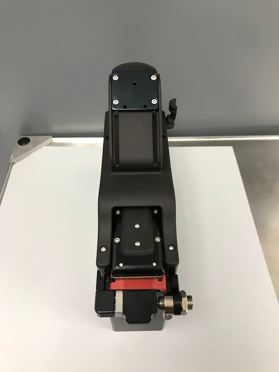
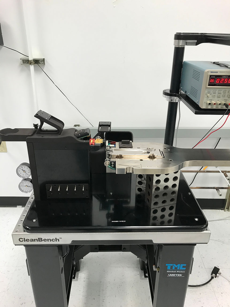
While interning at Tektronix Component Solutions (CSO), one of my main projects involved facilitating the procurement, organization, and assembly of a second iteration aligner system as shown below.

Early Design Changes
The first stage of this project was gathering operator feedback on the aligner system that was currently being used for package manufacturing. This process yielded a series of customer requirements that helped me navigate the design of the second iteration system. The preliminary updates included:
Adjustments on material choice and finish.
Redesign of nest securing method.
Small updates on epoxy drip tray design.
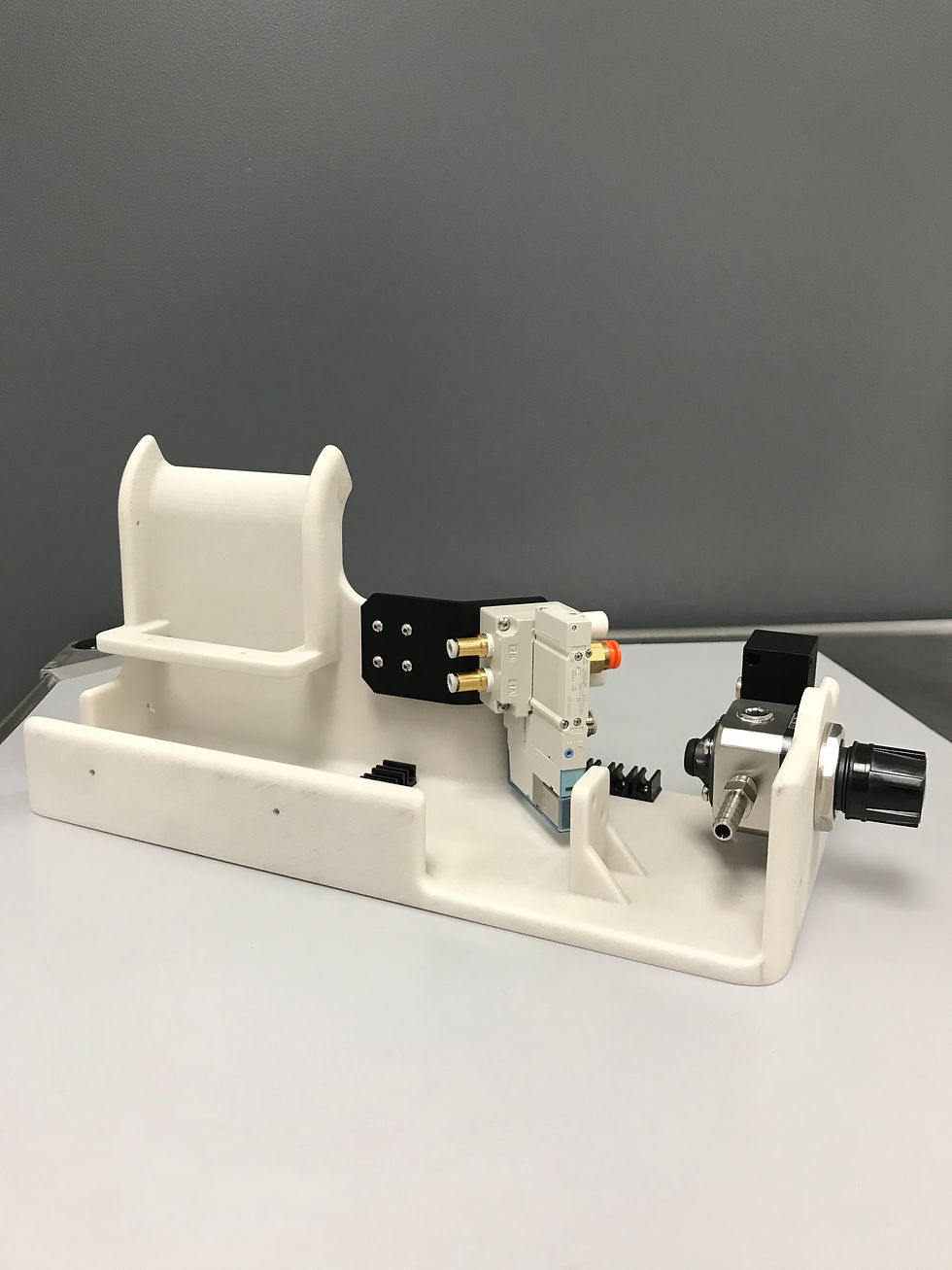
Changes to the pneumatic system.
Bill of Materials Generation
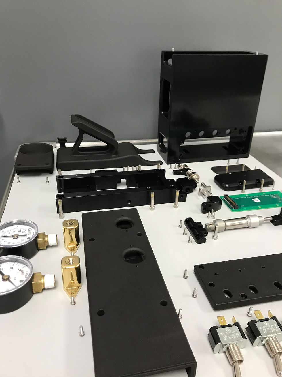
Due to the sheer magnitude of components within this project, the second stage was to get organized. I started by exporting the components from the master SolidWorks assembly to an Excel document. From there I began grouping components into specific sheets to allow for procurement status tracking giving me the ability to actively track the status of individual components. The main groups included:
3D Printed parts.
Machined parts.
McMaster parts
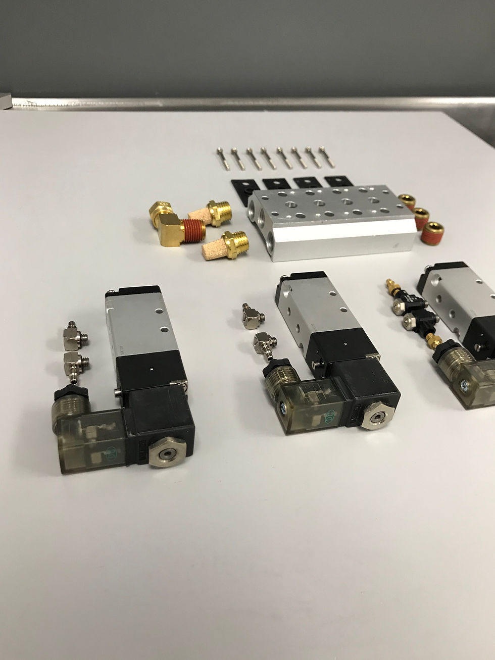
Additional and pneumatic parts.
My master bill of materials in Excel also had additional information that would be beneficial for the company if another aligner system needed to be built. These supplemental documents included:
Tapping Guide: Images of the various 3D printed components with visual indicators calling out tap size specifications.
Digital Organizers: Digital copies of the physical organizers used to store various hardware. Ensures in the event that organizers are lost spare components can be reordered.
I started organizing hardware by size and McMaster-Carr part number in a see-through organizer with labels. Although this process required a lot of upfront time it paid off during the assembly process. This system also allows operators to quickly locate common replacement hardware. Below is an image of my organizing method.

Vendor Selection and Request For Quote
Once preliminary design changes had been made I was able to begin working with vendors on manufacturing. This project involved meeting with the various vendors confirming our project intent and solidifying our designs in regards to material choices and finish. The four main manufactures on this project included:
GoProto: Selected for complex components requiring 5-axis machining and standard precision.
Jemtec: A local manufacturing company selected for high precision components.
Protolabs: Selected for all 3D printed components, leveraging Multi Jet Fusion (MJF) and Stereolithography (SLA) manufacturing processes.
Model Shop: An on-site machine shop selected for small-batch components of moderate complexity and precision.
Final System Assembly
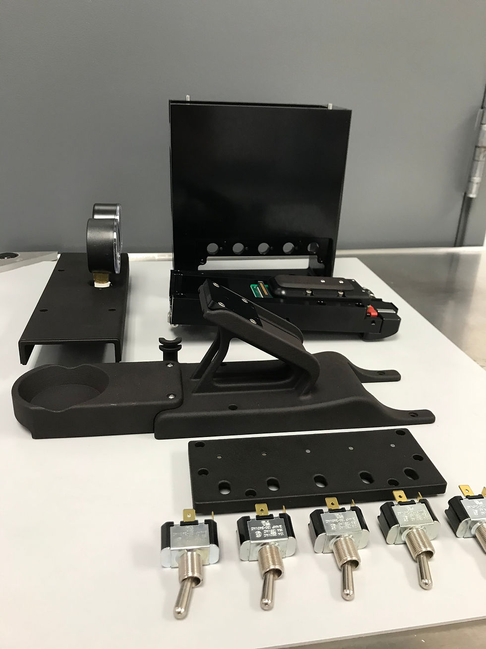
The last stage of this project was the final assembly. Once all the custom machined components and 3D printed parts had arrived on-site, I was able to begin assembling.
During the final weeks of my internship, I was able to completely assemble the aligner. Unfortunately, the hexapod positioning system hadn't arrived at this time. So I decided to use large machinist blocks to simulate the positioning system, which you can see in the fully assembled images below. With the aligner build finished I was able to begin testing the various pneumatic systems as well as my newly designed magnetic securing system.
Contributions:
Preliminary design changes of existing aligner system.
Designed an improved package securing mechanism.
Worked directly with vendors to manufacture custom hardware.
Facilitated the procurement of upwards of $50,000 in custom machined components and hardware.
Assembled functioning system ready for production deployment.
ALIGNER SYSTEM BUILD
